Today’s work began with some simple hole drilling in ½" square aluminum bar stock:

The bottle contains not water, but denatured alcohol, which I use as a cutting fluid. It prevents the gummy aluminum from welding itself onto the end of the drill bit, as it is prone to doing. I picked up the tip to use denatured alcohol from a Youtube video by a machinist in Germany, and it works really well.
The holes are offset an exact amount from one another:

I mentioned in the last post the use of collets, and for those readers who might be curious, here are a couple of the 444E collets, one ½" and one ¼", and collet nut:

The aluminum bar was then chopped off on the sliding table saw, and bolted up to one of the vise jaws with some ¼"-20 pan head screws:

The little Wiha ratchet you see above is part of a set I recently received for my birthday. After the Japanese ceiling project around New Years’, I realized a need for a tiny ratchet which fitted ¼" hex shank bits instead of the regular type of ¼" drive ratchet plus socket, which prove to be too large in confined spaces. the Wiha was my choice, and my wife came through with this little metal case of goodies:

It comprises more than 60 pieces, and utilizes a ¼" hex drive adapter to run tiny 4mm shank bits. But of course one can snap any old ¼’ shank bit into the tool no problem. There is an extension as well as an anti-static diver for use with electronics. It should prove handy from time to time.
The case is made of some nice thick metal too:

The set up complete, onto the woodwork we go. Up today are the hammerhead draw bars which joint the cabinet case to the support stand. The blanks were first prepared by the usual jointing planing resawing and super surfacing, followed by some work on the sliding tablesaw to cut to length and then kerf the pieces crosswise. At the end I had a pile of 9 pieces:

Only 8 pieces are required, however at last, with such small bits of wood, I could afford a spare piece. Such luxury!
The aluminum piece I had made earlier and attached to the vise jaw serves as a stop to register the piece in the vise:

After cutting both sides with a test pass, measuring the result and then adjusting the mill’s z-travel accordingly, I milled the pieces. The resulting neck dimension was right on target:

A while later, all 9 pieces were done without mishap:

Next step was to chamfer the perimeter of the hammer heads:

Then I used the sliding table saw with the blade canted over at 22.5˚ to chamfer the small ends of the draw bars:

It’s funny when you take the step of planning in an extra stick and nothing goes awry. But, 8 were all that were needs so one went in the trash.
Half of the draw bars were then fitted to the sill crosspiece of one of the stands:

A closer look at a couple of them:

Next step was to fit the same 4 draw bars to the bottom board of the carcase:

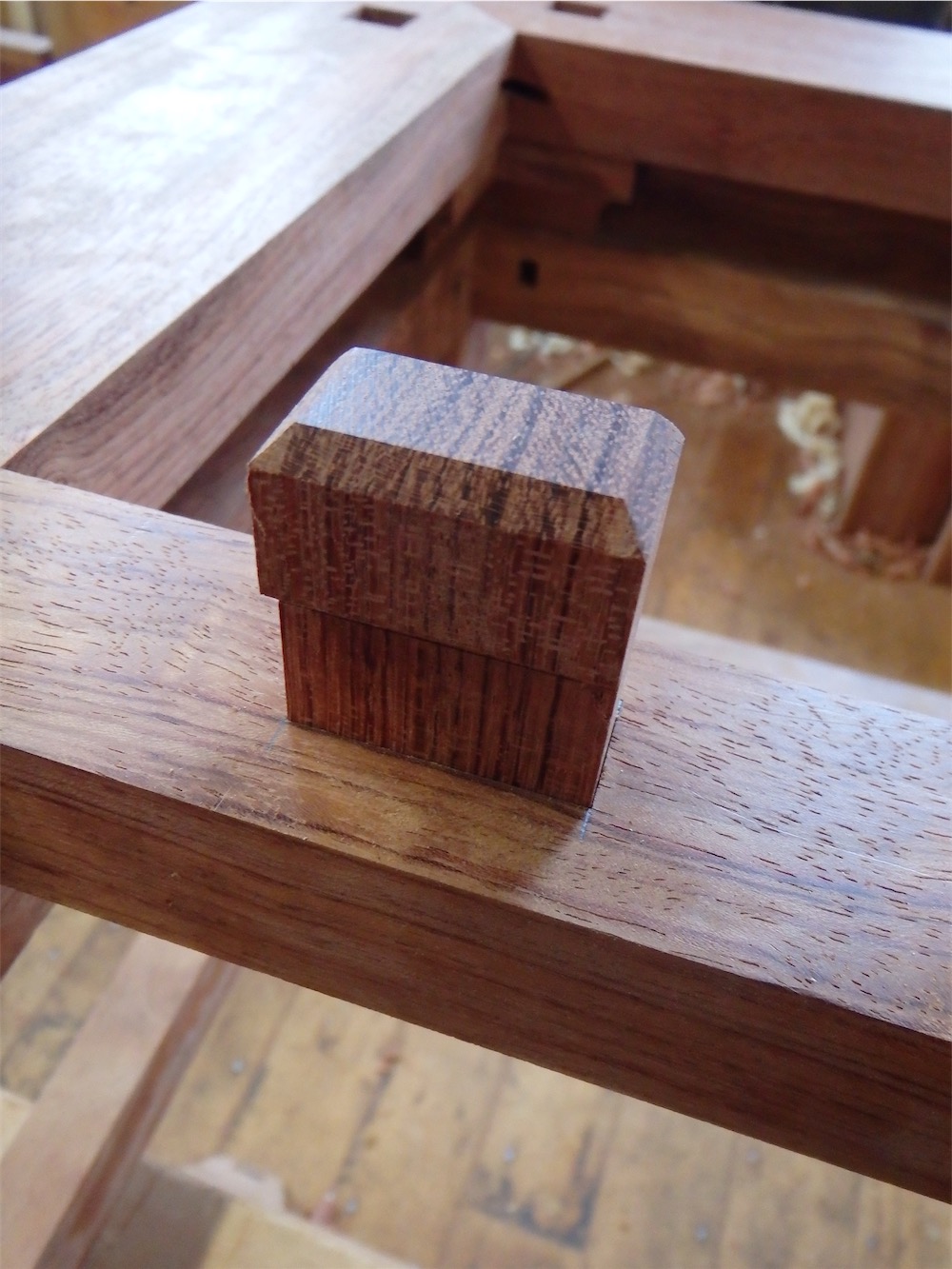
When installed, the hammer heads sit in a 3/8" deep recess, leaving a total of ¼" of the pin protruding:

Next was a step I’ve been awaiting for quite some time, namely placing the cabinet box upon the stand:

Similar to how I marked out the door hinge centers on the bonnet cornice piece previously, I employed a custom-machined brass transfer pin in place of the pivot pin at the bottom of the stile:

The door is positioned at the correct offsets and alignments, in preparation for marking the hinge center:

The draw bars were all driven down and into position and the location of the carcase relative to the sill was carefully measured to confirm it was where it should. Only minor tweaking was required, which was a good sign.
If you poke your head down below and look up, you can see where the hammerhead bars emerge:

These will be fitted with crosswise wedging pins very soon. I’m thinking I’ll use Gabon ebony for those wedges, if I have any kicking around.
Anyhow, the perfect world of the drawing for this cabinet had the hinge centers falling exactly upon the sill miter lines. I was curious to see how close i got to those lines after all the fabrication, of the sills themselves, the carcase, the hinge stiles on the doors, and the hinge pin centers on the door stiles.
The left side miter line first:
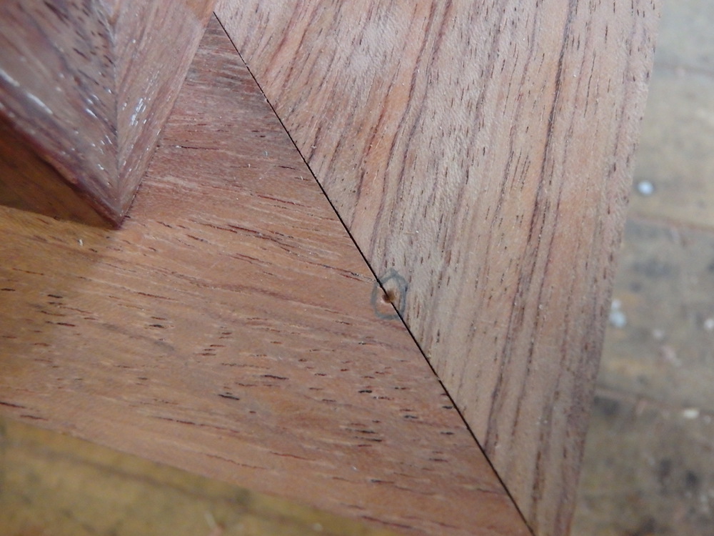
Don’t worry about the miter being slightly open, as the locking pin, or shachi sen, has yet to be driven into that joint. They will close up nice and tight soon enough.
The right side miter line was just missed by a hair with the center point:

Overall, I was very pleased with the way things turned out today:

While I was working on the above, interspersed were rounds of finishing work on the bonnet cornice assemblies which I had started last time (not illustrated). At this juncture, they have 3 coats of finish. I plan to put 5 coats on the very front edges of those assemblies, so these should be done in another day.
Tomorrow I’ll repeat the same process of assembling carcase to stand and marking out the door centers on the stand’s sill miters. Once that’s done I can proceed to drill out those places for the bronze bushing which will be fitted. I can also complete assembly of the sills themselves and get them into finish.
Thanks for visiting the Carpentry Way.
via Tumblr https://davidpires578.tumblr.com/post/159512126629
No comments:
Post a Comment