Fitting the long cap rail assemblies to frame #1:

I feel like I’ve been doing a fair share of mortising lately in getting these cap rails on. There’s a lot of joinery in this support stand, that’s for sure.
The cornice will have hammer-headed rods fitted to mortises with an internal step which serves as a stop:

Eight of these will lock the cornice down to the frame.
Here’s another corner:

These miters should close up tightly when the wedging pins, shachi sen, are fitted. I’m glad to have a decent fit at this stage, without any pins of wedges driven into position.
Frame 1 with cap rail fitted:

Now, next day, fitting cap rail assemblies to frame #2:
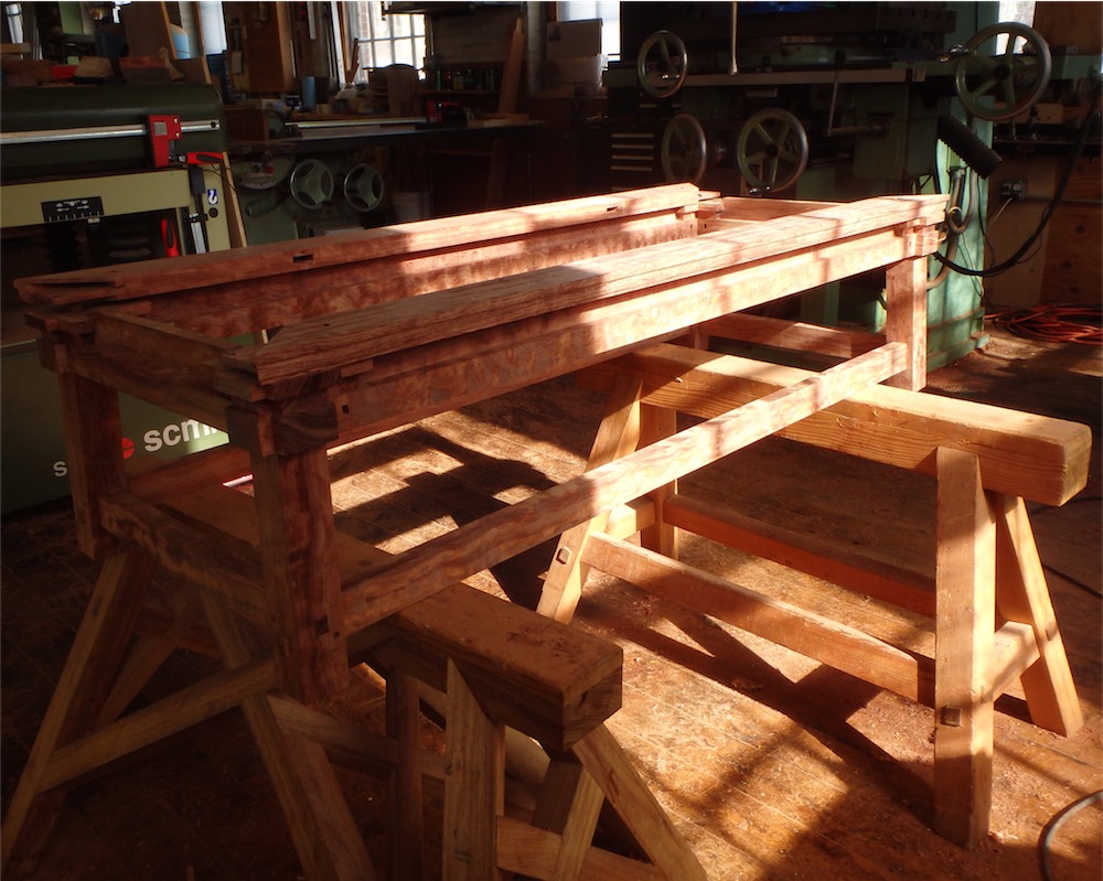
The light in the shop was especially nice at that juncture.
I needed to set the shaper up for a templet routing task, and thought a picture of the Aigner back fence assembly might be of interest to some:

Worked like a charm. That accessory is a $500 sort of thing, but it’s well worth it. It wouldn’t be hard to fabricate an approximation of it, but having the digital scale is nice.
The two stands, as they uh, stand now:

Another view:

Meanwhile, the shedua I re-sawed the other day was reduced some more, sheddua-ing a few pounds (is that the most ridiculously dumb pun?) to be sure, and here are the boards which will be the stock for the 18 drawer fronts I will make:

Today I also fitted the threaded inserts to the legs, and I made use of a special tool I designed to help with that job. ‘Tool’ sounds rather grand. I converted one of the spare leveler feet from prior milling operations to use as both a drilling and as a fastener-mounting jig.
Here is the drilling jig about to be placed in the end of the leg:

The slid down into in place:

A ½" brad point drill provided a flat-bottomed hole, and was fitted with a stop to control the depth:

Drilling compete:

The result:

The brad point dimple in the center is actually the surface of the tenon.
The following parts comprise the same drilling jig put to use as (grand title coming up…) a threaded insert fitting tool:

Yours for $29.95. Well, not too far off that actually… The parts comprise, left to right: a shouldered ½" bolt, the drilling guide jig, and 3/8" threaded insert.
Assembled for use:

The brass guide jig fits first in its mortise, slides down a short way until the end of the insert meets the start of the bored hole, at which point the allen key is put to use to thread the fitting in:

As the bolt is tightened down the jig is tapped and slid further down to keep increasingly better registration. It was important to me to put the insert into the leg in a straight line. I guess that much is obvious, huh? Previous methods I have tried in service of the same idea have gotten me close to a well fitted leveler foot, however sometimes the I found the line of the adjusting bolt in the leg was slightly misaligned to the insert, and the feel of the bolt turning slightly worse than I might like as things tightened into place. Functional, but not dialed in - that is the difference between the previous result and what I wanted. So, the more precise jig I developed ties together tasks of boring the hole and of fitting the insert. It was the next solution to try, and it seems to have worked well.
After a bit of trial and error with the leg removed from the frame so I could see what was afoot in the mortise, I determined that the underside of the head of the shouldered bolt needed to come down until it pinched a 5/32" (4mm) gage block:

Removing the jig, the insert is now at a reasonably precise - and repeatable - hole depth :

The depth of the insert is set so as to have the tip of the insert, all threads engaged, just about crest out at the lower end grain wall of the mortise - you can just make out the threaded insert tip in the photo:

I put the stretchers as low as I could for maximum strength, and the insert as far up as I could for strength. These hardware details can be a pain in the ass, but they need attending to or they can bite you in that same ass later on.
I cut up a little more shedua today. Here then is the stock for the back panels used on the upper sliding doors:

I was getting a bit of tear out from this material in the planer, whether taking 0.1" (2.5mm) passes or 0.03" (.7mm) passes, and even with skewing the board somewhat in the feed. I tried this and that, to no avail. Like the figured bubinga, I have to stay a good 1/8" (3mm) fat on each face with this material when at this stage of the milling. These boards will be decked in the mill next, as that will not tear out the wood.
And these are the leveler feet, now back from the machinist and with bronze thrust washers and extra thick snap rings fitted:
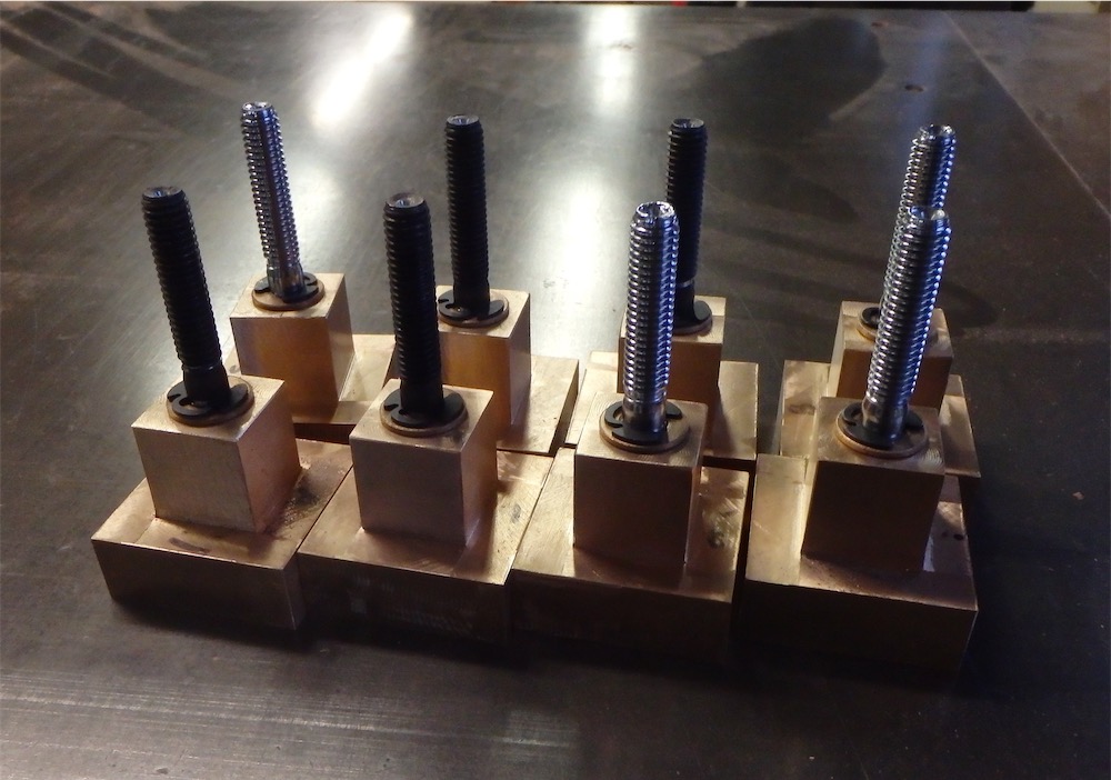
The bolts will be trimmed in length a fair amount, and I have to mill the compound bevel on the bottom of the foot yet. There’s a lot of little things involved with these leveler feet.
I’ll deal with that soon enough. All for today, I hope you managed to grind your way through with undue torment and distress.
via Tumblr http://davidpires578.tumblr.com/post/139203642624
No comments:
Post a Comment