I was thinking at first it was time to get working on the main beams for the support stand, however there was some work remaining on the pillow blocks and I decided I wanted to complete all the cut out on those components before moving onto other parts.
Each pillow block pair required a pair of mortises and a pair of angled notches:

After mulling over whether I would be better off using the hollow chisel mortiser or a routing approach for those small mortises, I elected to use a 7/16" up-cut spiral carbide in the milling machine, which is a slight bit undersize of final dimension.
The mortising went smoothly (not pictured), and I am left with some end wall paring to tackle in the near future.
The angled notches would have been troublesome to deal with except for a handy piece of equipment which recently arrived. In thinking over a few of the various angled cuts I have to make on various parts of the cabinet, and some of the different ways that might be accomplished - and which of those ways might prove to be the most versatile in terms of future work of a similar nature - I settled upon a machinist’s sine plate as the most accurate and widely-applicable option for me. Certainly it would be a notch up from cutting wooden angled wedges, making MDF hinged platforms, MDF contraptions upon which a router could be operated, and so forth, all approaches I have tried in the past to one degree of success or another.
I found a used 6"x12" sine plate, hinged on the long side, originally made by Suburban Tool. It is accurate to a few tenths (i.e., 0.0002" or so) and the price was at least digestible. I couldn’t have afforded a new one in this size.
Setting up a sine plate is easy so long as you are comfortable using a little bit of trigonometry. Here’s my set up for the angled notches on the pillow blocks, which are at a 20˚ angle from the horizontal (70˚ from the vertical):
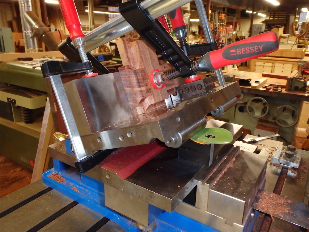
I’ve clamped a 3"x12" gauge block on the end as a taller support fence.
The center to center distance from the sine plate hinge to the point where the round support bars meet the deck is exactly 5". The tangent of 20˚ is 0.3639702…, so multiply that by 5 and you have the required rise, equal to 1.819851…“.
Once you have the rise figured out you then make up a stack of gage blocks and shims until you have that same value, and stick that stack under the support bar, as you can see above. There’s a swing arm on the other side of the plate which locks the setting in place. Suburban Tool’s design is nice in that regard as the swing arm does not protrude above the work surface.
In this case, the notch itself would have a slight clearance allowance, so strictly speaking it wouldn’t have mattered too much if I produced a 20.2˚ angle or a 19.8˚ angle. I suspect I was pretty close to the desired figure however, and would rather feel confident in knowing I was working to a closer tolerance rather than wondering if it would be close enough.
A 1-2-3 block was clamped into place to serve as a positioning stop, and the pillow block pair was clamped into place thusly:
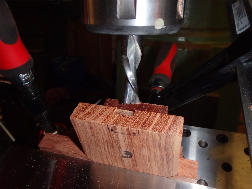
I’m using a down-spiral 0.5” carbide bit here to give crisp sidewall cuts around the notch,
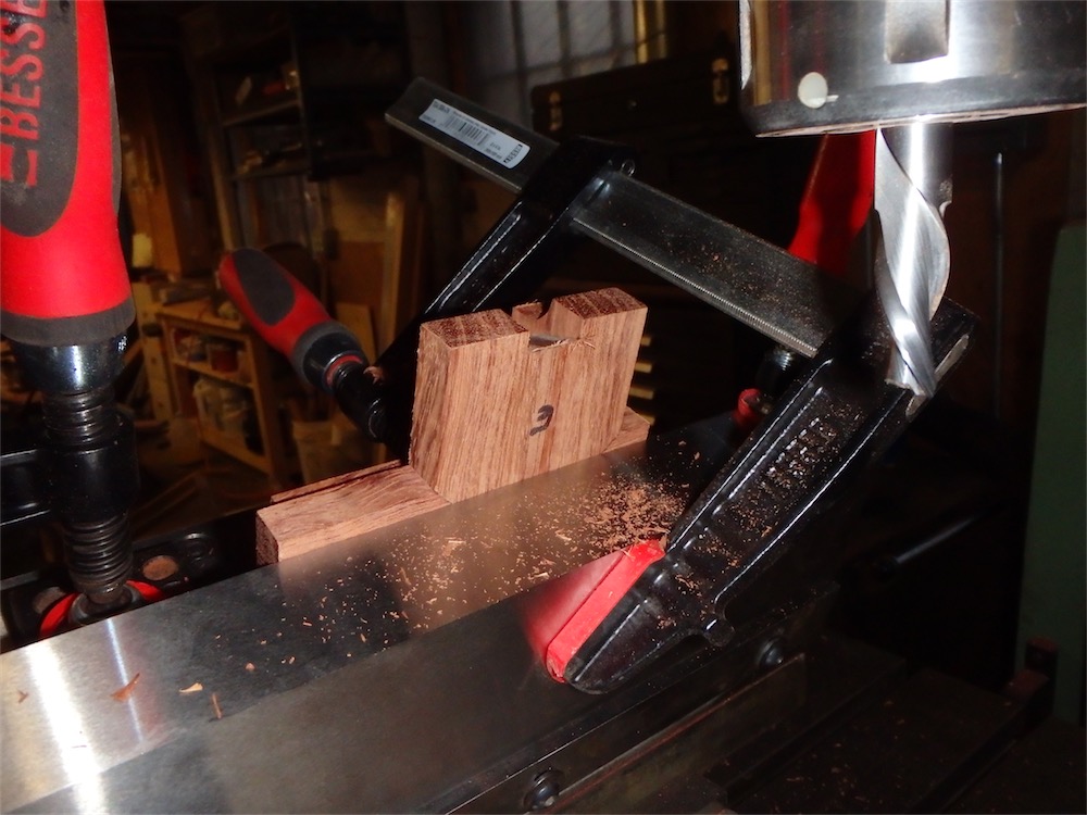
Another view - note that I have swung the rotary table around 90˚ so that I can use power x-travel while milling the notch instead of cranking the y-travel back and forth:

The back side of the set up, prior to taking another cut:

You can tell I’m not a regular machinist as I am using woodworking clamps to fix the work in position. I suspect a lot of machinists would have set up other clamping arrangements, and since I have a good assortment of T-bolts and nuts, along with adjustable risers and other hold downs, not to mention a cluster of Destaco products, it will hopefully just be a matter of time until I have gotten more used to using those things. The woodworking clamps certainly hold things okay, but what you want really is to have the clamping apparatus as out of the way of the cutter as possible. Learning as I go - what else is new?
Here, the cut has been made to the depth and width targets taken through a series of cuts and measures:
The machine’s DRO proved invaluable and saved me a lot of time. I made all the notches about 0.005" under dimension, aiming for a light interference fit later on when these pillow blocks are assembled to the inverted ’T’ beams.
The backside of a completed angled notch:

A later addition to eliminate tear out was a sacrificial block clamped onto the top face:

Another view:

The sine plate arrived yesterday in the mail and I was able to put it to use the very next day. I’m happy I have it now in my set, and I expect to use it with some frequency in my work. Probably one day I will obtain a larger compound sine plate as well (three plates stacked with two hinges).
At the end of the day the notches were cut and all the mortises:

A different look at the near-complete pillow block pair:

A while later, all 8 pairs were through this stage:

Tomorrow I will square up those mortises, which will complete all cut out on the pillow blocks. Then it will be on to those inverted ’T’ section beams, which have been worked upon previously.
All for now. Thanks for visiting the Carpentry Way.
via Tumblr http://davidpires578.tumblr.com/post/134560103659
No comments:
Post a Comment