Last post in this thread took place back in September.
After acquiring some fabulous shedua stock for the drawers, I have been sidetracked with other projects. In the past couple of weeks, I have been able to turn my attention to this sideboard build, which will likely consume the next 4-6 months of shop time. Not just shop time, a fair amount of home time as well, as that is where I do my CAD work.
The past 10 days or so have been largely about working through the drawing with a fine-tooth comb, in preparation for rough cutting of stock. This is one of those initial stepping stones across the river I must traverse to realize a successful outcome in this design build process. After so many hours have already gone into a design, and having received the go-ahead from the client, one could be forgiven for being eager to get to work slicing up the material.
However, in this case, maybe more particularly than with other projects, I am dealing with material which is more or less irreplaceable. Take a look around for wide and thick slabs of bubinga and you aren’t going to come up with much these days. The cessation of raw log exports from Cameroon, plus the economics of wood drying being what they are, have made the combination of wide and thick bubinga stock rather difficult to come by in what is otherwise a fairly readily available material.
I wanted to be totally certain about how I would slice and dice a slab like this:

About 600 lbs. of material lying there, 50" wide, 9’ long, and 3" thick. You only get one chance with cutting up a chunk like this.
While the design of the cabinet was largely resolved, as I worked on obtaining some take-offs of each part I began to have some second thoughts about one of the framing details.
Just for a refresher, here is that design as it stood in September:

The niggling detail that wasn’t sitting right with me was the negative space created by the pillow block layer on the support stand. The pillow blocks act as spacers between a pair of beams, atop of which the cabinet carcase would be placed.
While I liked the aesthetics of that arrangement, and the practical consideration of the even air circulation around the beams that associated, there was a drawback. The drawback is that the pillow blocks are little more than spacers, and thus only modestly tie together the two beams in a structural sense. What you have there is essentially a horizontally oriented ‘ladder’. And that ladder, when you get down to it, is not as optimally stiff as it might be be if an alternate structural arrangement were to be considered. A ladder is poor when it comes to shear loading, as would be experienced with weight bearing downwards.
Given that this is a sideboard, one with reasonable capaciousness in the volume of stuff that can be accommodated, it is not beyond the realm of consideration to see that the cabinet could become heavily loaded at some point in time. Added to this, there is time itself, a constant, as is gravity. What I fear is that over time the weight of the cabinet and its contents might tend towards deforming the middle of the cabinet slightly downward. I’m thinking the effects of this are the sort of thing that might start to accrue after 20, 30, or 40 years. Certainly, if you look at old furniture pieces in museums, one can find no shortage of examples where gravity and the proclivities of wood to move have made decidedly clear effects. And those effects are rarely if ever on the positive side.
The problem with some slight amount of deformation in the middle of the cabinet down the line is that it would have strong adverse knock-on effects in terms of the fit of the double bifold doors and the many drawers inside the cabinet. If the doors and drawers are to be fitted with reasonably close tolerances, then one also exposes the fitted parts to fitting problems if slight deformation in the surrounding casework were to occur down the line.
I concluded therefore that this area of the support stand framing was deserving of a second look.
While I had a certain attachment to the use of pillow blocks as a tie-in to the previously built side and coffee tables for the client, it was also obvious that from a normal standing position the pillow blocks were largely concealed from view. To get a look at the negative space framed by those pillow blocks would involve laying on the floor - after all, the support stand for this cabinet is all of 14" tall. In short then, the aesthetic aspect of the pillow blocks was a minor aspect.
From my understanding, for every increase in depth of a beam, stiffness is improves by a square of that increase. The current arrangement featured a pair of beams, one at 1.375" thick, and another at 1.125" thick, a total of 2.5" of material.
To wit:
For a beam with rectangular cross section, bending (flexural) strength is a function of the square (second power) of the depth (height). A similar, though more complicated, relation applies for I-beam shapes.From: http://www.structural101.com/Beam-Design—Basic.html
With all other factors the same, a rectangular beam with depth of 12 inches has a bending strength that is 4 times that of a beam with 6-inch depth.
Bending strength of the beam is dependent on the “section modulus”.
If you start looking at the most efficient arrangement of material to make a beam stiff, you end up at an 'I’ -beam. So, with that ideal in mind, I reconfigured the lower beam into an inverted ’T’ shape which tongues and grooves into the upper beam.
Here’s the revised lower beam form:

This change more or less gives the lower beam a depth of 3", so as to make a total of 4.125" for total depth of the two beams connected together. The previous design gave me 2.5" and now there is 4.125", an increase of 65%. Without going into detailed calculations, I can expect, as a ballpark, an increase in stiffness with the new arrangement on the order of 2.72 times greater than previous.
Aesthetically, the change is slight, and, as noted above, most of the change will be out of view until one’s eyes are below knee height:

The confluence of parts at the cabinet corner remains pleasing to my eye:

Feeling sufficiently confident about the design of the stand, and unlikely to make significant changes to the proportions of the cabinet carcase atop the stand, I felt I could start in on the cut out today of the parts comprising the lower stand.
The big slab was sufficiently heavy that I asked a couple of guys from the adjacent shop to help me lower it down to the floor. Once down, I marked some lines, snapped some ink down, and got busy with the larger Makita circular saw:

The board leaning against the posts is one of the wide Goncalo alves boards I am hoarding.
Able assistance to the cut out task was afforded by the larger re-saw:

Here are some of the rough-cut legs - keep in mind that I’m making two of these cabinets:

The rest lay piled up after cutting out - the stock for the front door panels, the stretchers, and what will be the inverted ’T’ section lower beams:

What remained from the slab was still a chunk, still pretty heavy, but entirely flatsawn:

The standing piece to the left, also 10/4 stock, is a piece left over from a Ming-influenced table I built a few years back. That material will be sliced up further to become part of these two cabinets.
The sawing was sufficiently vigorous that the Makita 380mm saw began to complain. Smoke is never a good sign. Stripping the machine down afterwards was straightforward however. It looks like I will need to replace the rear arbor bearing and the brushes:
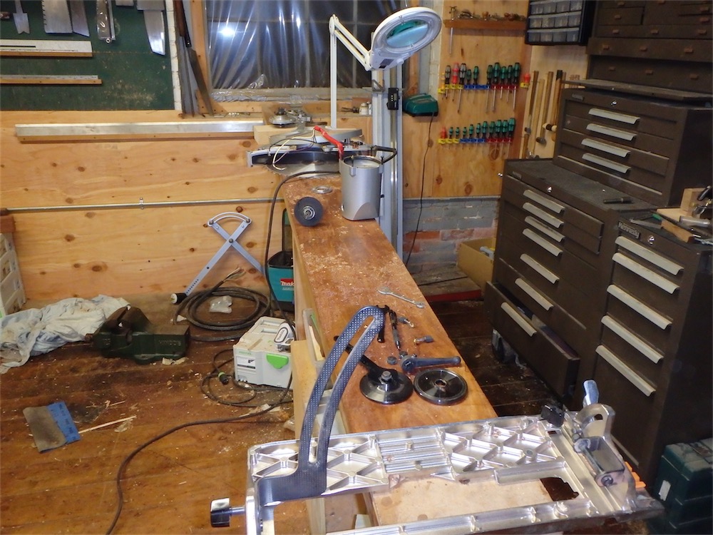

Both parts are fairly cheap and easily sourced, so hopefully this saw will be up and running in another week or so. Fortunately it got me through some critical steps today.
All for now. Be prepared for a bunch more posts on this thread as the build gets underway over the next few months.
via Tumblr http://davidpires578.tumblr.com/post/132972161719
No comments:
Post a Comment